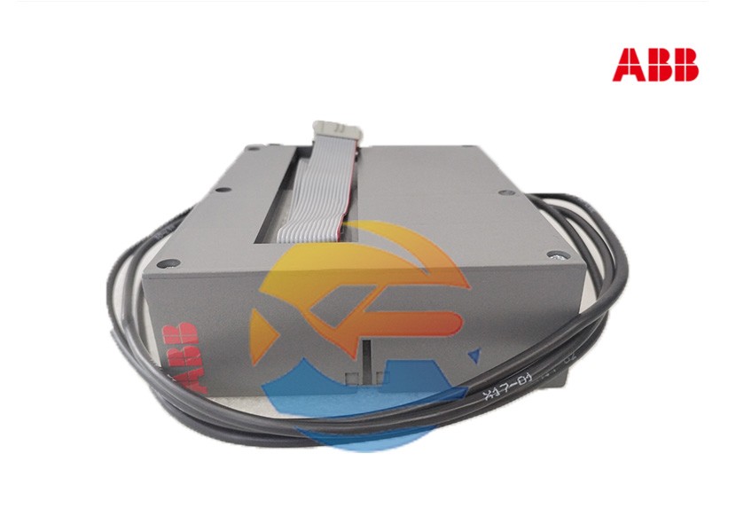
Specifying the right motor controller is the first step; its correct installation and configuration are what unlock its full potential. For panel builders and control engineers, integrating the ABB MCU2A02V24 intelligent motor controller requires attention to detail. This guide provides a practical, step-by-step approach to selection, wiring, and commissioning this advanced device.
Step 1: Selection and Pre-Installation Checks
1. Verify Compatibility and Sizing
Before ordering, confirm the controller is suitable for your application:
- Motor Full Load Current (FLC): Ensure the MCU2A02V24's current rating range covers your motor's full load current. The device is available in different frame sizes (e.g., for motors up to 12A, 32A, etc.).
- Supply Voltage: The "V24" denotes a 24V AC/DC control supply. Verify this matches your control circuit voltage. Other variants are available for different voltages (e.g., 110V AC).
- Communication Needs: Confirm that the integrated Modbus RTU protocol is compatible with your master system (PLC/SCADA). If not, an optional communication gateway may be required.
2. Gather Necessary Components
You will typically need:
- The ABB MCU2A02V24 unit.
- A compatible contactor (the MCU2A02V24 controls the contactor's coil; it does not carry the main motor current itself).
- A three-pole circuit breaker or fuse for short-circuit protection upstream of the controller.
- Shielded twisted-pair cable for the RS-485 communication network.
Step 2: Physical Installation and Wiring
Warning: Installation must be performed by a qualified electrician with the system completely de-energized.
1. Power Circuit Wiring
- Main Power In: Connect the three-phase power supply (L1, L2, L3) to the input terminals of the MCU2A02V24.
- Main Power Out: Connect the output terminals of the controller to the main contacts of the contactor.
- Contactor to Motor: Connect the output of the contactor to the motor.
2. Control Circuit Wiring
- Control Supply: Connect the 24V AC/DC supply to the designated A1/A2 terminals.
- Digital Inputs: Wire your control devices (e.g., a Start button and Stop button) to the digital input terminals. The module can be programmed to assign functions to these inputs (e.g., Start, Stop, Reset).
- Output Relays: The device has relay outputs.
- Trip Relay ( normally open): Use this to signal an alarm condition to a PLC or a warning lamp.
- Ready/Healthy Relay ( normally closed): Use this to indicate that the controller is powered and healthy.
3. Communication Wiring (RS-485 Modbus)
- Use a shielded, twisted-pair cable (e.g., Belden 3105A).
- Connect the 'D+' and 'D-' wires from the controller to the corresponding data lines of the Modbus network.
- Terminate the Network: Install a termination resistor (typically 120Ω) at the first and last device on the RS-485 network to prevent signal reflections.
- Connect the Shield: Ground the cable shield at one end only (usually at the master device) to avoid ground loops.
Step 3: Configuration and Commissioning
1. Basic Parameter Settings
Using the front-face buttons and display, configure the essential parameters:
- Motor Full Load Current (FLC): This is the most critical setting. Set it exactly to the value on the motor nameplate. All thermal protection calculations are based on this value.
- Trip Class: Set the trip class (e.g., 10A, 20A) according to the motor's starting characteristics and required tolerance for temporary overloads.
- Protection Functions: Enable or disable specific protections (e.g., earth fault, jam) and set their pickup levels and time delays as needed.
2. Communication Setup
- Node Address: Set a unique Modbus slave address for each MCU2A02V24 on the network (e.g., 1, 2, 3...).
- Baud Rate, Parity: Configure these communication parameters (baud rate, data bits, stop bits, parity) to match the settings of the Modbus master device.
3. Testing
- Functional Test: Without motor power, simulate start/stop commands and verify the contactor operates.
- Primary Injection Test: Use a test set to inject currents into the controller to verify that it trips accurately at the configured overload and fault settings.
- Communication Test: From the SCADA/PLC system, read a simple register (e.g., motor current) to confirm the communication link is working correctly.
Conclusion
Integrating the ABB MCU2A02V24 is a systematic process. By carefully selecting the device, following correct wiring practices, and meticulously configuring the parameters, you can ensure that this intelligent controller provides not only robust motor protection but also valuable operational data for the entire lifecycle of the motor.
