How to Select and Wire the ABB 1TGE120028R0010 Timing Relay: A Practical Guide

How to Select and Wire the ABB 1TGE120028R0010 Timing Relay: A Practical Guide


view:    time:2025-10-14 23:23:03


Selecting the right component is one thing; installing and integrating it correctly is what leads to a successful project. For engineers and electricians working with the ​ABB 1TGE120028R0010​ timing relay, a methodical approach ensures reliable operation. This guide provides a practical, step-by-step overview for selecting the appropriate variant, understanding its wiring, and integrating it into a control circuit.
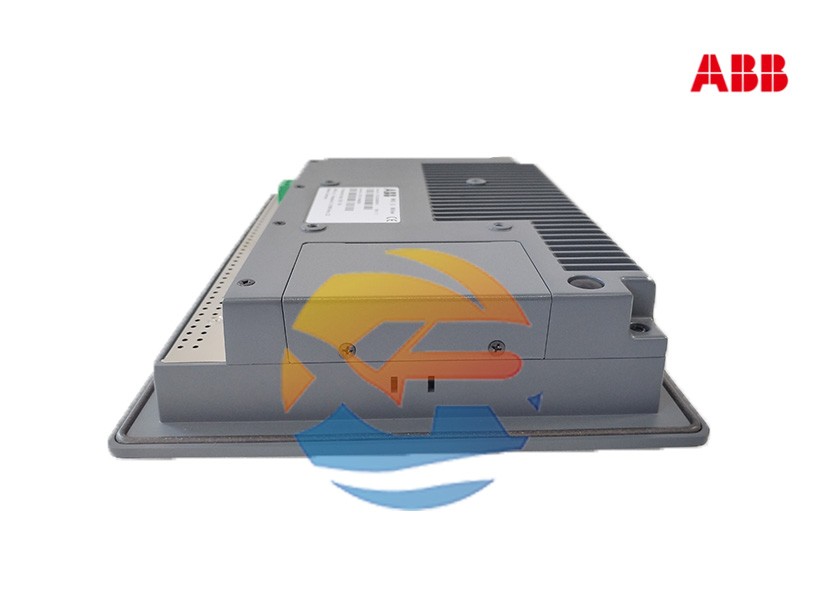
ABB 1TGE120028R0010

Step 1: Selecting the Correct Variant and Understanding the Part Number

The part number ​1TGE120028R0010​ is a base order code. It's crucial to specify the exact timing function and range you need. ABB's CR-M series offers a wide range of variants identified by suffixes.

Key Selection Criteria:​

  1. Timing Function:​​ What do you need the relay to do?

    • On-Delay (TDE):​​ Delay after energization.
    • Off-Delay (TDD):​​ Delay after de-energization.
    • Interval Timer:​​ Immediate pulse for a set period.
    • Flicker/Impulse:​​ For flashing lights.
  2. Time Range:​​ What is the required delay? Ranges can be from 0.06s to 600h, or longer. You must choose a relay whose maximum range comfortably exceeds your needed delay for better accuracy.

  3. Supply Voltage:​​ What voltage powers the relay's coil? Common options are 24V AC/DC, 110V AC, or 230V AC. The coil voltage must match your control circuit voltage.

  4. Contact Configuration:​​ How many and what type of contacts are needed? The standard model often has changeover contacts (1 CO or 1 C/O).

Always consult the official ABB CR-M selection guide or datasheet to choose the correct full product code based on these criteria.​

Step 2: Physical Installation

The relay is designed for easy installation on a ​35mm DIN rail. Simply hook the top of the relay onto the rail and snap the bottom into place. Ensure there is adequate space around it for heat dissipation and access to the terminals.

Step 3: Wiring the Relay

Safety First:​​ Always isolate the circuit from all power sources before wiring.

A typical wiring diagram for an ​On-Delay​ function is as follows:

  1. Power the Coil:​​ Connect the control supply voltage (e.g., L1 110V AC) to the designated coil terminal (often labeled A1 or A2). Connect the neutral (N) to the other coil terminal.
  2. Connect the Load:​​ The output contacts will be labeled with numbers (e.g., 15-18 for a changeover contact).
    • To use the ​Normally Open (NO)​​ delayed contact: Connect your power source for the load to the common terminal (15). Connect the device you want to control (e.g., a contactor coil, a lamp) to the NO terminal (18).
  3. Operation:​​ When the control signal energizes the relay coil, the timer starts. After the set delay, the contact between terminals 15 and 18 closes, energizing the load.

Step 4: Setting the Time Delay

The relay features a time-setting dial. This may be a rotary knob with a scale or a series of dip switches for fine-tuning.

  • Rotary Knob:​​ Turn the knob to the desired delay value on the scale. The scale is multiplicative. For example, if the range is 0.1s - 10s, and you set the knob to 5, the delay will be 5 seconds.
  • Dip Switches:​​ Some models use a combination of dip switches to set the time in a binary fashion. Refer to the datasheet for the exact coding.

Step 5: Testing and Commissioning

  1. Visual Check:​​ Ensure all wiring is secure and correct.
  2. Apply Power:​​ Restore power to the control circuit.
  3. Verify Operation:​​ Trigger the control signal (e.g., close a switch). Observe the relay's LED indicator. It should light up immediately, and after the set delay, you should hear an audible click as the contacts change state.
  4. Measure Output:​​ Use a multimeter to confirm voltage appears at the output contacts after the delay.

Conclusion

Integrating the ​ABB 1TGE120028R0010​ into a control panel is a straightforward process of correct selection, careful wiring, and thorough testing. By following this guide and always referring to the official product documentation, you can reliably implement precise timing functions that are crucial for the safe and efficient operation of industrial machinery and systems.