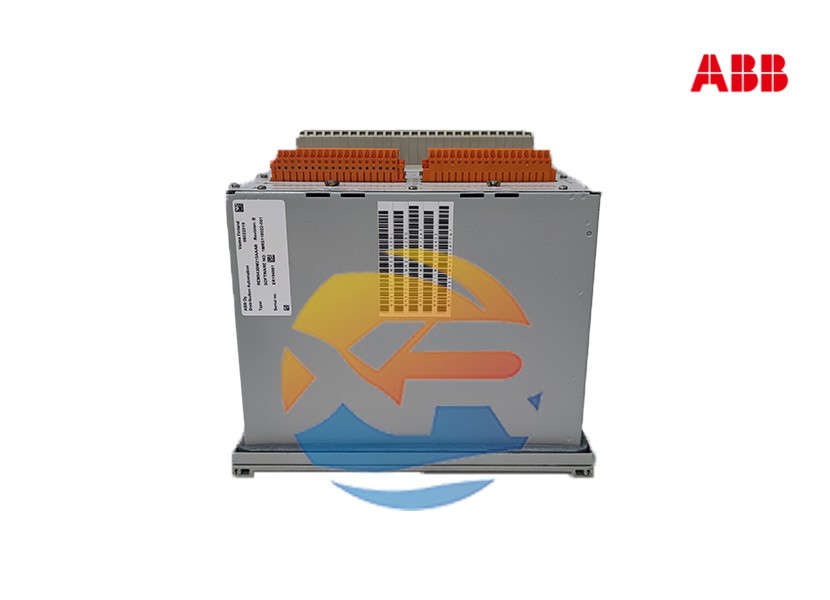
Specifying the right protection relay is the first step; its successful integration is what ensures system security. The ABB REM543BM215AAAB is a sophisticated device, and its implementation requires careful planning. This guide provides a practical, step-by-step approach for engineers and technicians, covering the key considerations for sourcing, configuring, and commissioning this advanced digital relay.

Pre-Integration: Planning and Verification
Warning: All work on protection relays must be performed by qualified personnel following strict safety protocols.
Step 1: Verify Application and Compatibility
Before procurement, confirm the REM543BM215AAAB is suitable for your specific application.
- System Parameters: Check the rated current of the connected Current Transformers (CTs) and Voltage Transformers (VTs). Verify that the relay's power supply (indicated by the "M215" code, typically 110-240V AC/DC) matches your panel's auxiliary supply.
- Communication Network: Determine the required protocol (e.g., IEC 61850, Modbus TCP) and ensure the network infrastructure (switches, gateways) is compatible.
Step 1: Sourcing the Authentic ABB REM543BM215AAAB
To avoid the severe risks of counterfeit components, follow these guidelines:
- Source from Authorized Distributors: Purchase exclusively from authorized ABB distributors. This guarantees a genuine product, full manufacturer warranty, and access to technical support.
- Verify the Full Part Number: The exact order code is REM543BM215AAAB. Confirm this with your supplier. Even a single character difference can signify a different configuration.
- Check Lifecycle Status: Consult ABB's official product documentation to ensure the product is in the "Active" phase of its lifecycle, ensuring long-term support and availability of spares.
Step 2: Hardware Installation and Wiring
- Panel Mounting: The relay is designed for standard DIN rail mounting. Ensure there is adequate space for ventilation and wiring.
- De-energize: Ensure all AC and DC power sources to the panel are isolated and locked out.
- CT/VT Wiring: Connect the secondary circuits from the CTs and VTs to the appropriate terminals on the relay. Crucially, ensure CT secondary circuits are never left open-circuited, as this can create dangerously high voltages.
- Binary Inputs/Outputs: Wire the binary inputs (e.g., circuit breaker status, external commands) and the output relays (for trip, close, alarm signals) according to the wiring diagram.
- Communication and Power: Connect the Ethernet or serial communication cable and finally, the auxiliary power supply.
Step 3: Software Configuration with PCM600
The relay is configured using ABB's PCM600 engineering tool. This is a powerful, standardized environment for the entire Relion® product family.
1. Create a Project and Connect
- Create a new project in PCM600.
- Connect your engineering laptop to the relay's service port or via the station network.
- Let PCM600 automatically detect the connected relay and read its current configuration.
2. Configure Hardware and Communication
- In the hardware configuration, verify that the detected module (REM543BM215AAAB) matches the physical device.
- Set the communication parameters: Assign an IP address, subnet mask, and gateway for Ethernet communication. Configure the protocol settings (e.g., IEC 61850, including the logical device name and data set mappings).
3. Set Protection Functions
This is the core of the configuration. Navigate to the "Protection Functions" section in PCM600.
- Enable Functions: Activate the required protection functions (e.g., Phase O/C, Earth-fault).
- Set Parameters: Enter the calculated setting values for each function. For example:
- Overcurrent Pickup (I>): The current level at which the protection starts to operate.
- Time Dial/Curve: Select the characteristic curve (e.g., IEC Standard Inverse) and time multiplier to achieve coordination with other devices.
- Define Logic: Use the built-in Configuration Editor in PCM600 to create custom logic. For instance, you can define how a binary input can block a protection function or how an output relay should be activated.
4. Set Disturbance Recording
Configure the pre-trigger and post-trigger time for the disturbance recorder to ensure it captures the data before, during, and after a fault.
Step 4: Commissioning and Testing
- Secondary Injection Test: This is mandatory. Use a modern test set to inject simulated currents and voltages into the relay. Verify that:
- Measured values on the relay's display and in PCM600 are accurate.
- Each protection function operates at its exact set value and within the specified time.
- The correct output relay energizes to trip the circuit breaker.
- Functional Testing: Test the control logic by simulating binary inputs and checking the outputs.
- Communication Test: Verify that the SCADA system can read measurements, receive alarms, and execute control commands.
Conclusion
Integrating the ABB REM543BM215AAAB is a systematic process that bridges electrical engineering with software configuration. By meticulously following these steps—from sourcing authentic hardware to rigorous testing—you can ensure this powerful relay will perform its critical protective role reliably, safeguarding both personnel and electrical assets for years to come.
