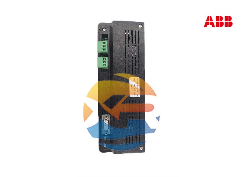
Specifying a controller like the ABB FPR3203526R1002A is the first step. Its successful integration into a control system requires careful planning and execution. This guide provides a practical, step-by-step overview for system designers and engineers, covering the key considerations for system architecture, software configuration, and commissioning of this modular controller.

Pre-Design: Is the FPR3203526R1002A the Right Fit?
Before procurement, confirm that this controller meets your project's requirements. It is ideal for:
- Medium to Large Applications: Requiring a significant number of I/O points.
- High-Reliability Needs: Applications where redundancy is a consideration.
- Harsh Environments: Where wide temperature ranges and immunity to electrical noise are critical.
- Integration with ABB Ecosystems: Particularly within an ABB DCS or with other ABB automation products.
For smaller, standalone machines, a more compact controller might be more cost-effective.
Step 1: System Architecture and Component Selection
The FPR3203526R1002A CPU module is part of a larger system. Key components to specify include:
1. The Baseplate/Backplane
The CPU and other modules slot into a baseplate (rack) that provides power and the communication backplane. You must select a compatible baseplate with enough slots for all required modules.
2. Power Supply Unit (PSU)
Select a compatible and appropriately rated Power Supply Unit for the entire rack. For high availability, a redundant power supply configuration is recommended.
3. I/O Modules
The flexibility of the system comes from the I/O modules. You will need to select the appropriate modules based on your field device signals:
- Digital Input (DI): For reading signals from switches and sensors.
- Digital Output (DO): For controlling actuators, valves, and relays.
- Analog Input (AI): For reading signals from transmitters (e.g., pressure, temperature).
- Analog Output (AO): For controlling devices like variable frequency drives.
- Specialty Modules: For specific needs like thermocouple input or high-speed counting.
4. Communication Modules
If the required network connectivity (beyond the CPU's built-in ports) is needed, add communication modules for protocols like PROFIBUS DP, DeviceNet, or additional Ethernet ports.
Step 2: Software and Programming
The controller is programmed and configured using engineering software.
1. Engineering Tool: Automation Builder
The modern tool for programming ABB controllers is ABB's Automation Builder. This integrated suite supports hardware configuration, programming, simulation, and debugging.
2. Hardware Configuration
The first task is to create a hardware configuration within the software that mirrors your physical setup. This involves adding the CPU (FPR3203526R1002A), defining its parameters, and adding all the I/O and communication modules in their correct slots.
3. Control Logic Development
Develop the application program using standard IEC 61131-3 programming languages supported by the tool:
- Function Block Diagram (FBD): Ideal for process control loops.
- Structured Text (ST): For complex algorithms and calculations.
- Ladder Logic (LD): Familiar to electricians, good for discrete logic.
- Sequential Function Chart (SFC): Perfect for batch or sequential processes.
Step 3: Installation, Commissioning, and Maintenance
1. Installation Best Practices
- Follow EMC Guidelines: Use proper grounding, shielded cables, and segregate power and signal cables to prevent noise interference.
- Environmental Conditions: Ensure the control cabinet environment (temperature, humidity) is within the controller's specified range.
2. Commissioning Procedure
- Download the Application: After hardware is powered up, download the configured program from Automation Builder to the CPU.
- I/O Checking: Methodically check every input and output point to ensure field devices are correctly wired and responding.
- Functionality Testing: Test control loops, sequences, and interlocks thoroughly before full operation.
3. Lifecycle Management and Support
The ABB FPR3203526R1002A is a specialized industrial component. For long-term success:
- Source from Authorized Distributors: To guarantee authenticity and avoid counterfeit components.
- Plan for Spares: For critical applications, consider purchasing spare modules to minimize future downtime.
- Maintain Software Backups: Keep secure backups of the application program and hardware configuration.
Conclusion
Integrating the ABB FPR3203526R1002A is a structured process that bridges hardware design with software engineering. By carefully planning the system architecture, correctly configuring the hardware, and rigorously testing the control logic, engineers can build a highly reliable and scalable automation system that meets the demanding needs of modern industry.
