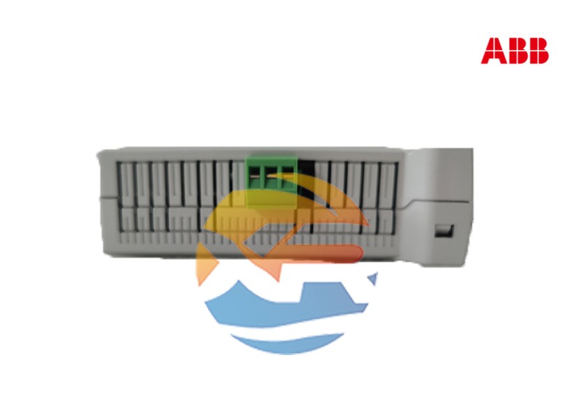
For maintenance engineers and panel builders, dealing with a critical component like the ABB 520PSD01 power supply module requires practical knowledge. While its operation is mostly automatic, proper selection, installation, and routine testing are essential for long-term system reliability. This guide provides a hands-on, step-by-step approach to sourcing the correct module, integrating it into a control rack, and establishing a preventive maintenance routine.

Pre-Procurement: Verification and Compatibility
1. Confirm System Compatibility
The 520PSD01 is designed for specific ABB control systems, primarily the Advant OCS series (e.g., MasterPiece 200/200C stations). Before ordering, you must confirm:
- Compatible Rack/Station: Verify that this PSU model is approved for use in your specific station model (e.g., an S100 or S400 station). Using an incompatible module can lead to improper fit, connection issues, or even damage.
- Firmware/Version: Check if there are different versions of the 520PSD01 and which one is required for your system.
2. Determine the Required Configuration
- Standalone vs. Redundant: Decide if you need a single module or if you are setting up a redundant (N+1) system. For redundancy, you will need to purchase multiple modules and ensure the rack supports this configuration.
- Input Voltage: Confirm the input voltage rating of the module (e.g., 120V AC vs. 240V AC) matches your plant's auxiliary power supply.
Step 1: Sourcing the Module
- Source from Authorized Distributors: To guarantee you receive a genuine, new product with a valid warranty, purchase the 520PSD01 from an authorized ABB distributor or a reputable supplier specializing in industrial automation parts. The secondary market for obsolete components carries a high risk of counterfeit or refurbished units that may fail prematurely.
- Check Lifecycle Status: The Advant OCS platform is a mature system. Check the product's lifecycle status on ABB's official support website. If it is classified as "Classic" or "Limited Support," plan accordingly for potential future migration and source necessary spares.
Step 2: Installation and Wiring
Warning: Installation must be performed by a qualified electrician following all local safety regulations (e.g., NFPA 70E). Ensure all power sources are disconnected and locked out/tagged out (LOTO) before beginning work.
- Power Down: Completely isolate and lock out the AC power feeding the entire control rack.
- Module Insertion: Carefully slide the 520PSD01 module into its designated slot in the rack. Ensure it is firmly seated and engages correctly with the backplane connector. Most modules will have a locking lever or screw to secure them in place.
- AC Power Wiring: Connect the AC Line and Neutral wires to the designated input terminals on the module's front. Follow the wiring diagram precisely. Ensure the connections are tight.
- Redundancy Configuration (if applicable): In a redundant setup, all PSU modules must be connected to independent AC power sources if possible. This provides protection against a failure of a single AC circuit. Connect the modules according to the manufacturer's redundancy guidelines.
- Alarm Contact Wiring (Optional): Wire the module's fault relay output (usually a Form-C contact) to a digital input on the controller or a central alarm panel. This provides immediate notification of a PSU failure.
Step 3: Commissioning and Testing
After wiring is complete and double-checked:
- Apply Input Power: Energize the AC power supply to the rack.
- Verify Status LEDs: The module's "Power Good" or similar LED should illuminate. In a redundant setup, "Load Share" LEDs may also indicate proper operation.
- Measure Output Voltage: Use a multimeter to measure the DC output voltage at the test points on the module or the backplane. It should be within the specified tolerance (e.g., 5.1V DC ±1%).
- Test Redundancy (Critical Step): This is the most important test for redundant systems.
- Simulate a failure by switching off the AC power to one of the 520PSD01 modules.
- The control system should continue to operate without any interruption. The healthy module should take over the entire load, and its fault alarm should activate.
- Restore power to the failed module. It should seamlessly re-join the redundant system.
Step 4: Maintenance and Troubleshooting
A preventive maintenance schedule is crucial for critical infrastructure.
- Regular Visual Inspection: Check for signs of overheating, bulging capacitors, or dust accumulation that can impede cooling.
- Annual Performance Test: Repeat the output voltage measurement and redundancy test during planned shutdowns.
- Common Issues:
- No Output, Fault LED On: Check input AC power and fuses. The module may have an internal fault.
- System Resets Intermittently: Could indicate a failing PSU that cannot handle the load under peak demand.
- Redundancy Alarm Active: Indicates a failure or imbalance in one of the redundant PSUs.
Conclusion
Proper handling of the ABB 520PSD01—from careful sourcing and correct installation to regular testing—is straightforward but non-negotiable for system reliability. By treating this power supply as a critical asset and following a disciplined maintenance approach, you can ensure it provides years of reliable service, forming the bedrock of a stable and highly available industrial control system.
